
The Travel Map
Touch to light up your journey.
Problem
You have a beautiful paper world map on the wall where you used push pins to mark all the cool places you have been to. But, it’s moving day, you still haven’t figured out how to move this giant piece of paper with 50 loose pins on it that contain all your data showing how cool you are. It would be nice if you had a travel map that was easier to carry around!
Solution
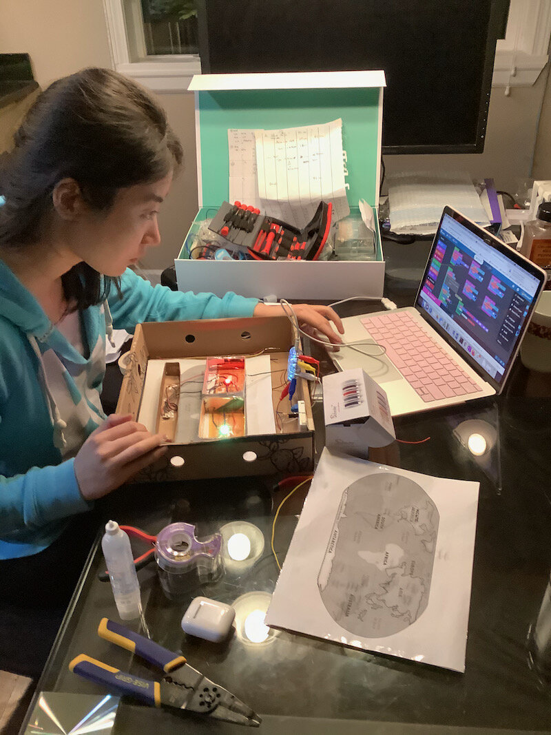
I decided to make a prototype of an interactive travel map. The purpose of the travel map was to track the traveler’s travel history. The original idea was that there is a physical map and a digital map and data on the two maps can sync up. The physical map can serve as a great decoration piece or a conversation starter for friends or family who come to visit a traveler's home. The digital map allows travelers to easily share their travel history online.
As a proof of concept, this CPX-based prototype is using continents instead of cities/countries. The map can be turned on when flipping the switch to the right; light and sound will be played as feedback. When a user pushes a continent on the map, the continent will light up with sound indicating that it is registered or deregistered based on the length of the push. Users can use the knob (potentiometer) to adjust the brightness of the continents’ backlighting on the map.
Map On
Map Off
My Tools
Circuit Playground Express (CPX)
Breadboard
Potentiometer Knob
Alligator Clips
Flora NeoPixel
Conductive Thread
Wires
Aluminum Foil
2XAA Portable Battery
Cardboard Box
Paper & Pen
Tape and Scissors
What I Did
Come up with product features and requirements
Plan for different phases and timeline of the work
Design the hardware connections
Implement (code and physically build)

Process
I. Planning
After defining the features I wanted for the map, I broke them into 3 phases of work, so that I could ensure the key functionalities are prioritized and delivered within the constrained timeline. I drew the system diagram to help me think about what I needed to satisfy the phase 1 requirements of the prototype.
System Disgram
Circuit Diagram
II. Preparation
I drew the circuit diagram to think through what hardware I needed to accomplish phase 1.
III. Design Testing
In order to make sure my design worked, I first tested the hardware with simple code to make sure the individual continents would work. Then I connected the continents and tested the code that would allow them to work together. In this way, I was able to test my plan to use controls and push sensors together.
Test Light Source
I originally tested with LEDs, which required more CPX pins and separate wired connections for each LED. I then switched to Flora NeoPixels, so that I could control individual pixels through code while having all the pixels attached through a single positive and negative wire.

Testing LEDs in light-constraining boxes
Simplified the wire connection using NeoPixels
Testing Pressure Sensor and Light
When pressing down on a continent, the light behind it should light up. The pressure sensor worked, but I did 4 iterations to get the somewhat ideal light effect.
1st: With LED lights, the brightness is concentrated in the middle, which makes it hard to see the whole continent's shape.
2nd: With NeoPixels, the brightness spread out but the light was too weak to show through the paper clearly.
3rd: In order to show the continent outline, I created small holes along the border of the continents.
4th: I created the holes with the paper map and the foil paper glued together so the two layers are perfectly aligned to make the light come out nicer.

Testing my self-made pressure sensor and light effect

Testing how much light would be revealed through the each continent of the map

The final light effect

Connected all the wires and lights to test the code and hardware connections.
Test Code and Wire
Before sewing each NeoPixel to the box, I tested the NeoPixel with my code to make sure they could be individual controlled after I connected them with a single power wire and ground wire.
Plan Wire Path
After testing all the NeoPixels and confirming they would work as expected, I started to draw the wire paths on the cardboard boxes to plan for the routes the wires would follow.

Marked and cut the boxes where wires pass through.

Planning for the wire paths.
IV. Implementation
After multiple testing on the code and hardware connections, I cut, soldered, or twisted tie the wires where needed and taped everything in place to minimize connection issues.

Final Prototype
